![]()
IntroductionGrand piano rebuilding can allow for the quality service life of worthy instruments to be extended significantly. However, for rebuilding truly to be effective, the technician must adopt a logical and analytical approach to the work. It is not sufficient simply to recreate shortcomings in design which may have been built into the piano at the time of manufacture. While the practice of rebuilding exactly as original might seem to be safer, it will surely produce mediocre results in many cases. The technician should develop a personal philosophy of design, which will evolve as his/her piano rebuilding proficiency increases. The development of a design philosophy will, in many respects, parallel the situation which exists with progressive piano manufacturers, where an understanding of good design is an evolving art. We must be open minded, and continually searching for better ways to execute the skills of our discipline.
At Overs Pianos, we have been rebuilding concert grand pianos since 1988. Over that period our work procedures have evolved as the scope of work undertaken has increased. The process of rebuilding progresses in a familiar pattern, beginning with the initial inspection of the piano, transferring the inspection results onto a computer 'estimate sheet', through an evaluation and consultation process with the piano owner, and if accepted by the client and ourselves, to the final execution of the rebuild.
The following notes discuss the principle considerations and procedures which are, in my view, critical to the success of a grand piano rebuild.
Selecting Suitable Pianos for Rebuilding - soundboard, scale and action considerations
As specialist grand piano rebuilders, we are often called to asses pianos for rebuilding. Our advice will, in many instances, result in the client upgrading the piano or alternatively, investing a considerable sum to rebuild the existing instrument. The advice of a consulting technician is critical in guiding the owner to an appropriate course of action. Obvious factors to be taken into consideration include; the ultimate performance potential of the instrument, the opportunity cost of achieving that performance when compared to the cost of replacing it with a piano of similar quality, and the particular needs of the client.
There would seem to be little sense in recommending that a client should spend a large sum on a rebuild when he/she is too old or frail to play the piano effectively. In such a case, it might be appropriate to recommend that a moderate repair be undertaken, improving the piano's performance to the client's satisfaction, without spending months on an extensive rebuild.
On the other hand, if a pianist is performing at an advanced level, it would be inappropriate to recommend that an extensive repair be undertaken on an original condition one hundred year old piano. A proficient pianist should, ideally, have a piano capable of complementing his or her playing ability.Scale Design
When assessing pianos for rebuilding, the inherent design attributes of a piano should be taken into consideration always. Consider the following two scenarios;
a) A high quality piano, structurally sound and skilfully manufactured, but with a 'poor' scale design, resulting in poor tuning stability under variable climatic conditions, is offered for rebuilding.
b) A medium quality commercial grade piano, structurally sound but 'just satisfactorily' manufactured, is offered for rebuilding. This piano might have several workmanship shortcomings, but an excellent scale design will enable it to exhibit good tuning stability from season to season, and a relatively even tone across the compass of the instrument - without any serious soundboard impedance problems.
If pianos a) and b) were both manufactured with quality materials, and both were subsequently rebuilt by a competent rebuilder, it would follow that piano b) would exhibit superior tuning stability, with a more even tone quality. A consultant technician might present a case against rebuilding piano a), since it will probably exhibit poor tuning stability following a rebuild. Furthermore, any poor tuning stability might well be attributed to the rebuilder, since the original piano is reputed to be a quality instrument.
On the other hand, piano b) would probably perform very well after a rebuild, exhibiting superior tuning stability. Since the pin block might now be well fitted, the bridges repaired or replaced (and sealed), the down bearing (originally quite uneven) adjusted for a uniform light load on the sound board and the bearing bars appropriately shaped and hardened. The piano may prove to be very stable, with a pleasing and even tone quality.
Consulting technicians should be very selective when choosing pianos for rebuilding. Reputations are hard earned and easily lost. A poor choice of instrument, expertly rebuilt but with mediocre performance, will surely damage a rebuilder's reputation.
When considering the merits of different scale designs, I believe it is worthwhile for the technician to acquire a database of a range of piano scales, to develop a sense of what constitutes good design. For example, we have lost interest in rebuilding grand pianos where the long bridge scale changes to bichord covered strings just prior to the cross over to the bass. Any computer analysis of such existing scales (unfortunately there are a large number) will show that it is impossible to achieve a good crossover of inharmonicity, percentage of breaking strain and power when the stringing scale steps from trichord plain to bichord covers on the same bridge. I suspect that the unfortunate rash of pianos with this design scenario is a result of a long held design phobia against moving the break further up the scale. It should be obvious to any designer, should he/she care to interpret scaling spreadsheets, that when any 183/185 cm piano is designed with note B27 as the lowest note on the treble bridge and with a speaking length of around 117 cm (which is about the maximum length which can be fitted into a piano of this size), that the piano will have a very low percentage of breaking strain at the cross over, and poor tuning stability. Yet the number of six foot grand pianos which are designed this way is disturbing. Many technicians speak about experiences tuning such pianos, which exhibit pitch instability at the bass-treble break. The percentage of breaking strain deviation is the single most important causal agent of this malady. Yes I know that down bearing is important, but it is important elsewhere in the scale also. The fact that tuning instability occurs most often where there is greatest deviation in the percentage of breaking strain is not accidental. The two most common areas of the scale with a tuning stability problem are the bass/treble cross, and the cross between string sections on the long bridge (where designers often compromise the speaking lengths adjacent to the bars, to make the bridges easier to manufacture). These problems are largely scale related.
In 1989 we conducted a scaling experiment with a Welmar rebuild to test my theory (which I had discovered with the aid of my pocket calculator in the pre-computer days of 1985). The Welmar six foot grand is unusual in the world of six foot pianos, since the lowest long bridge note is D30 with a speaking length of 111 cm. While a 111 cm D30 is not remarkable, the D30 part is. Most other designers seem to be stuck crossing at B27 (Blüthner, Boston, Kawai, Yamaha and Samick are five that come to mind - and there are many others). However, since the Welmar plate web between the bridges is very thick and 150 mm wide, the possibility of cutting out part of the plate adjacent to D30 got me interested, as I was eager to replace the bridges with an improved scale. While this involved cutting out a section of the plate web to make room for the longer string scale at D30, there was room. I decided to increase the string length from 111 to 117 cm at D30, which is longer than note D30 on a Steinway model D (115.2 cm). Therefore, the redesigned Welmar scale would have less deviation in the percentage of breaking strain across the entire string scale, when compared to a standard D. The Welmar rebuild proved to us that percentage of breaking strain was the critical factor leading to poor tuning stability in otherwise well constructed pianos. The success of the 1989 Welmar rebuild (illustrated at the bottom of the 'brief history' section on this site), lead us to design an improved scale for a Steinway D rebuild in 1990 (we have used our improved D scale on two other rebuilds since). This piano again reinforced our views on scaling and tuning stability.
Bridge Placement and Sound Board Impedance
Potential soundboard impedance problems should be assessed prior to committing to any rebuild. It is good practice for technicians to assess to the tonal balance across the entire compass of an instrument before stripping it for repair. Experienced rebuilders develop the discretionary skills required to determine where there are soundboard impedance problems and scaling shortcomings in an original design, even though the instrument might be in a poor condition. When these problems are encountered, a range of appropriate modifications should be considered and a plan of action determined prior to committing to a repair. Any planned modifications should be included in a work estimate spreadsheet to determine the repair viability. While there are many pianos which might be repaired with design modifications to produce a satisfactory outcome, each proposal should be compared to the opportunity cost of purchasing a new instrument of equivalent quality.
As a consequence of poor bridge and/or rib placement, many pianos exhibit sound board impedance problems which cannot be rectified by voicing or hammer strike point adjustment. This problem is common at the bass/treble crossover and at the section breaks along the long bridge (especially when the bridge height has been reduced to allow for bar clearance). The characteristic tone associated with low soundboard impedance has come to be known in our workshop as 'ducks disease', since these 'short tone' notes have a tonal character which causes them to 'quack' like a duck. A low impedance at the end of the long bridge can be improved by lengthening the bridge past the last note, to extend the length of the soundboard/bridge contact to cover the next soundboard rib. Low impedance can also occur between string sections when the bridge height has been reduced to clear the bar. Strengthening the bridge at the point of weakness can improve the situation. Some manufacturers attach a stiffening block to the soundboard behind the bridge at the reduced height section. Furthermore, they often position the adjacent soundboard ribs equidistant from bridge cut-outs to facilitate the installation of the stiffening block. When considering possible solutions to sound board impedance problems, each 'board must be individually assessed in a holistic manner.
A Case Study of a Quality Piano with a soundboard problem
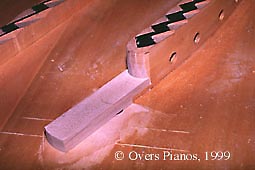
Some time ago we rebuilt a 223 cm grand piano, where the lowest note on the long bridge was B27 (this in itself is not a criticism). The long bridge terminated (at the bass end) 225 mm out from the inner rim, and mid way between two soundboard ribs (traditionally, in a well designed piano, the bridges should terminate over a sound board rib). A low impedance problem at was quite evident at B27. I attributed this to the bridge terminating 225 mm from the rim without employing a ring bridge to control the impedance, and that it terminated between two sound board ribs. We decided to extend the end of the long bridge 65 mm, under the adjacent bass plate-bar. After modification, with the bridge now terminating over the last sound board rib in the bass corner (and a little closer to the rim), the impedance problem all but disappeared. The bridge extension was fitted using a scarf joint prior to recapping the bridges. This allowed for a very tidy modification.
Soundboard impedance mismatch is often a problem at the crossover notes of the bass bridge. Again, this is often from a bass bridge placement which is too far out towards the middle of the board. The tone becomes very 'woofy' and 'full', with a lack of upper harmonics. When considering the placement of the treble end of the bass bridges on many modern pianos, a listening test often will reveal that there is a low impedance problem just prior to the crossover to the long bridge. This impedance will be lowered further if the sound board is tapered adjacent to the bass bridge at the crossover, producing a serious mismatch in soundboard impedance between the two adjacent break notes of the bass and treble bridges. When rebuilding pianos with this problem, we extend the bass bridge to the soundboard rib beyond the original end of the bridge. This effectively stiffens the board, while at the same time moving the end of the bridge slightly closer to the rim -which also raises the impedance.
If bridges are placed too close to the inactive edge of the sound board or belly rail, a high impedance situation develops. The tone will lack fundamental harmonic and the decay time will generally increase. These problems are also a result of poor original design. It is sometimes possible to correct or improve this problem, if the bridge is not too close to the sound board perimeter, by tapering the sound board towards the edge where it meets the inner rim or the belly rail (as the case may be). Piano rebuilders be vigilant, if you rebuild as instrument with an impedance problem which is not rectified, and the instrument fails to impress when rebuilt, the blame will be passed directly to you. You will be 'wearing' a problem which was not totally of your creation. Be absolutely certain that you can make a worthy instrument from any rebuild proposition. Do not allow a client to talk you into a rebuild if you're worried about the outcome.
Where should the bridges be placed on the sound board ?
After twenty years of piano rebuilding, I have come to a preferred option regarding the placement of the bridges on the sound board. If you don't agree with my views, I would welcome your comments via email. In general, at note A1, I prefer to see at least 175 mm of clear soundboard from the end of the bass bridge to the edge of the inner rim - the Steinway D has a full 250 mm, a very satisfactory figure. In many contemporary designs, the tenor end of the bass bridge is placed much further out on the soundboard than the lower end of the long bridge. I cannot understand designers doing this, since these two bridge ends are transmitting frequencies which are only one semitone apart. How can the respective tonal quality of these 'adjacent' end-notes sound anything alike if they are placed at entirely different distances from the edge of the sound board - with different impedance values? I am going to resist publishing my preferred distances here. However, it should be obvious that each bridge end position should rest on the soundboard where there is a similar soundboard impedance value.
The theoretical ideal of placing the long bridge in the centre of the soundboard can only be largely achieved if a substantial cut off is positioned at the bass end corner adjacent to the belly rail. Generously proportioned cut off bars were commonplace in some of the Richard Lipp grands of the late 1800's. Fazioli has used substantial cut offs in some of his models to good effect. I confess that we are only now getting into soundboard replacement, and are yet to certify the benefits of cut offs in our own soundboards. But my observations of various instruments over the years has lead me to conclude that the cut off makes a significant contribution to quality tone - and soundboard control.
The long bridge has been placed at various distances from the bent side concave, over the history of the piano. This is a measurement which has developed some significance to me, as an indicator of effective soundboard area in the mid section of the long bridge For instruments made during the late eighteen hundreds, this measurement was typically around 280 mm. The earlier Yamaha C3 - C5 grands from the sixties had a figure of around 280 mm. Stienway D pianos have around 330 mm. Modern designs such as the Baldwin SD-10 and the C7F have around 350 mm. There are of course significant exceptions to the norm (eg. the Bosendorfer Imperial seems to have about a 'decent sized football field' of soundboard area everywhere, but of the instruments I have known and serviced - two in particular - they did not seem to be noticeably more powerful, if at all, in spite of the generous soundboard area). However, by and large the above figures tend to indicate where the soundboard area has been going over the past century. The Baldwin SD-10 piano in particular, when carefully put together with its standard soundboard design, is capable of outstanding performance. We rebuilt a circ. 1975 SD-10 in 1988, and I think it had perhaps the finest tone of any piano we have rebuilt to date. The SD-10 employs a large, but straight, cut off bar across the bass corner.
There has been much discussion on the PTG list over the past two years about the 'killer' octave of the second top section of certain pianos. It does seem that there is considerable variation in the distance of the long bridge from the belly rail of various instruments. Furthermore, the long bridge is actually closer to the belly rail than the bent side, at the second top section for most instruments. While it may be true that the position of the bridge influences the tonal quality, I would be just as inclined to suspect that the front duplex lengths, which occur only in the upper two sections, might be just as responsible for the inferior tone in this section of many pianos. We have rebuilt several pianos where we have removed the front duplex, replacing it with a hardened low profile bar which was located much closer to the capo' bar. The tonal qualities of these instruments was very much improved -in fact, the tone was/is excellent. I therefore suspect that the position of the long bridge at the two upper treble sections is of less importance when compared to its location at the lower end of the long bridge, and for the bass bridge overall. When one considers the frequencies produced at the various bridge sections this is not surprising. The bass end of the soundboard, from which the low frequencies are developed, will be required to move with considerably greater relative amplitude to speak effectively, whereas the upper treble, from which the higher frequencies are developed, will be required to move with a very small amplitude relative to the sound pressure level which is developed. Indeed, if the treble soundboard area is too flexible, the decay time of the treble will be altogether too short (ie. the soundboard impedance will be too low). In general, the further the bridge is located from the edge of the soundboard, the lower will be the soundboard impedance, and vice versa. This is the very reason why the treble end of the bass bridge will produce an inferior tone if it is placed too far out towards the center of the soundboard. This problem will be further aggravated if the sound board is wider across the bass area, eg. the upper end of the ****** six foot bass bridge is located well out on the soundboard. Furthermore, the ****** soundboard, if measure square from the straight side across the bent side, and over the treble end of the bass bridge, will measure around 950 mm (this is 50 mm wider than a typical grand piano soundboard). The full (perhaps slightly over-full) tone of the ****** at this area of the scale is, according to my observation, a consequence of its bridge layout.
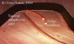
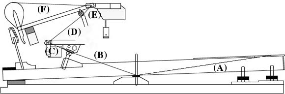
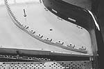
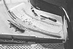
Presently, we are rebuilding a 7'4" commercial grade piano with a typical impedance problem at the treble end of the bass bridge (though not a bad as some). Not only was this piano designed without any extension on the bass bridge at the treble end, but to further complicate matters, the designer positioned a set bolt hole directly at the end of the bass bridge (this is guaranteed to aggravate any impedance problem). We moved the set bolt across to the belt between the bass and treble bridges, plugging the original hole and extending the bridge out over the next soundboard rib (a wooden block was fixed the back post for mounting the set bolt in its new position). We ground off the set bolt boss from the underside of the frame to make room for the bridge extension. We are expecting a marked improvement in the crossover of this piano. I like the scale of this piano. With a speaking length of 147 cm at note B27 (the last note on the long bridge and a very high break for a 225), this piano has less deviation in the percentage of breaking strain across the string scale (by about 10%), when compared to any of the typical modern 274 - 278 concert grands (183 cm at note F21 - four manufacturers use this same scale break note and speaking length - perhaps they all want to sound the same?). We expect this piano to be transformed from a commercial grade piano with basically good design, to a first class instrument following its rebuild. Images below are of the above mentioned piano.
The above paragraph was written in early 1999. I can now report that the modifications made to this piano (illustrated below), transformed it into an excellent instrument with an almost flawless bass/treble cross. The tapered soundboard perimeter worked incredibly well. Note that the soundboard tapering stops short of the treble end of the bass bridge. This was deliberate, since the upper bass bridge is really too far away from the rim in this design. The soundboard remains at its original 10 mm thickness adjacent to the upper bass bridge while it is tapered to 6 mm adjacent to the lower end of the long bridge. This, in conjunction with the bass bridge extension which raises its impedance at the treble end, allows for the tonal quality to be balanced between the two bridges. This piano now has a bass (with a new string scale) which is the equal of a 275 concert piano. It certainly was the equal of our 274 hire concert grand.
Bridge extension - the sound board impedance fix. Image showing tapered soundboard
Agraffes and 'String Noise'Agraffes are a significant source of 'string noise' in modern pianos. This is not a recent problem. Many high class piano makers have used agraffes with a steel pin insert in an attempt to achieve a 'cleaner' tone. I remain dissatisfied with the available production brass agraffes. We have experimented with various agraffe designs, including the inserted steel pin type, replacing the original pins with hardened steel pins. This proved to be unsatisfactory, as the strings would slide sideways on the hardened pins to the edge of the hole, only to resume 'noise' production activities.
We have now use two approaches depending on the severity of service expected. Where pianos are subjected to low or moderate use, we recut the agraffe string holes to a specially developed profile, while at same time modifying (mostly reducing) the string bearing angles, where they are excessive, to prevent excessive deformation of the agraffe string holes.
When a piano is expected to encounter severe service conditions, eg. heavy use, requiring three or more tunings per week, we have manufactured special agraffes of a more robust design. These are manufactured from a alloy steel(of similar hardness to piano wire). These agraffes are exceptionally 'clean'. We also reduce the string approach angle from the tuning pins to the agraffes, to reduce the risk of premature wire failure.
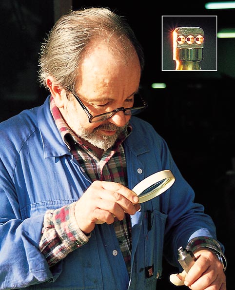
Wal Sullivan checking the machining quality of a sample custom agraffe.Please click on above image to view full size in a separate browser window
The String Approach Angle - to Capo' Bars and Agraffes
Excessive string angles at the capo' and duplex bars and agraffes, can have a deleterious effect on tuning stability and string service life. At various times, pianos of all qualities have been manufactured with string angles which are excessive, placing extreme loads on the capo' and duplex bars. This increases the risk of strings grooving the bars and agraffes, and of string breakage. I regard any string approach angle over 20 degrees to be excessive. When we reshape and harden duplex and capo' bars during a rebuild, the string approach angle is adjusted to 12 - 15 degrees, where possible, by reducing the height of the front duplex bar. However, the hardness of castings become increasingly softer towards the centre. Therefore, bars must be hardened after they are lowered. We adapted a hardening process for this procedure in 1994.
WARNING!
WHEN ALTERING THE SHAPE AND/OR HARDNESS OF DUPLEX AND CAPO BARS, OR WHEN ALTERING THE STRING APPROACH ANGLE, ENSURE THAT YOU POSSESS AN UNDERSTANDING OF PIANO DESIGN SUFFICIENT TO EXECUTE SUCH MODIFICATIONS. OVERS PIANOS WILL NOT BE HELD RESPONSIBLE FOR INCITING A TECHNICIAN TO MODIFY ANY PIANO. TECHNICIANS WHO CHOOSE TO UNDERTAKE ANY MODIFICATIONS DO SO AT THEIR OWN RISK.
The Shape and Hardness of Capo' and Duplex Bars
The production of 'clean' piano tone is dependent upon the appropriate shape and hardness of string bearing points.
I have come to suspect that recently manufactured pianos have softer duplex and capo' bars than those produced earlier this century. This is may be a result of improved foundry practice. The earlier green sand moulds contained some moisture, shortening the freeze time, to produce harder bars. The use of modern synthetic moulding sand binders allows the foundryman to produce moulds which are free of moisture. These allow the molten metal to freeze more slowly, producing softer bars. The piano wire tends to cut into the softer bars. The string grooves formed prevent the string from vibrating freely. The string tends to vibrate on the bar, generating string noise, and the considerable friction which develops as the string is pulled through the string groove impedes the tuning process. Under these conditions, the technician will have difficulty equalising the tension of the several string segments between the tuning pin and the hitch pin. The speaking length is the only segment about which the technician can gauge any measure of the tension (by listening to the pitch). Setting the tension of the other segments must be a matter of; the skill the tuner, and a minimum of friction at the bearing bars. Friction at the bars will ultimately be determined by the shape of the bearing bars and their hardness.
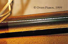
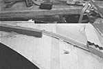
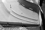
A reshaped capo', unhardened '93 rebuild
Note the grooves cut by the treble wire.
This piano was repaired again in 1998
- when the bars were hardened.A height reduced, reshaped and hardened capo'.
Note the original bar height can be seen at the
far end of the bar. 1996 rebuild.
Action Geometry and the Hammer/key Ratio
When considering the repair of a grand piano with a roller notch action, technicians need to be aware that the hammer/key ratio varies considerably from piano to piano, including contemporary instruments. The hammer/key ratio must be known prior to determining the appropriate size (ie. weight of) hammer set.
The accepted hammer/key ratio of modern piano actions, nominally 5.0:1, varies in practice from 5.5 for Kawai KG series pianos, to 4.7:1 for concert grand pianos from Steinway and Fazioli. Smaller grand pianos from earlier this century, such as the 1906 Steinway 5'10" grand piano, have a hammer/key ratio as high as 7.7:1. Pianos with a higher than 'normal' action ratio will require a lighter weight hammer set to achieve an acceptable touch weight. The use of a 16 lb hammer set on one of these earlier instruments will result in an unsatisfactory down weight averaging approximately 65 grams. Adding lead weights, to the keys, will not rectify this situation. Any attempt to correct the touch weight with lead will result in excessive key inertia. It will cripple the action response. Selecting the correct hammer weight for the hammer/key ratio is one of the basic rules of piano rebuilding.
Concert grands, with a lower hammer/key ratio of 4.7:1, allow the use of the heavy 19 or 20 lb hammer sets. Actions with a lower hammer/ key ratio will require a deeper than normal key dip for sufficient 'after touch'. When you next see a Steinway tech' set up a concert piano, check out the actual key dip setting. The key dip gauge might measure 9.8 mm, but the real key dip setting will invariably measure between 10.25 to 10.5 mm. We use 10.25 to 10.5 mm as our standard key dip setting for Steinway and Fazioli concert grand pianos. While it is possible to achieve a satisfactory 'after touch' by reducing the hammer blow distance, such an approach will result in less available power for the pianist.
The Kawai KG series pianos, with a hammer/key ratio of 5.5:1, are 'quite heavy' to play when fitted with a 16 lb hammer set. A smaller hammer set, or to adjusting the ratio to just less than 5:1. The ratio can be altered to 4.97 by moving the capstan position 5 mm along the key towards the balance pin. The wippen heel position and height will require adjustment to minimise friction between the capstan and the wippen heel. The formula for calculating the hammer/key gear ratio is as follows;Hammer/key ratio = (Balance pin hole to capstan center)/(Key front to balance pin hole)* (Wippen flange center to jack-roller center point)/(Wippen flange centre to capstan center)* (Hammer centre to hammer core center)/(jack-roller center pt. to hammer centre)
Hammer key ratio = (B/A)*(D/C)*(E/F)Action geometry and friction
These notes will be written after the July 2000 Australasian Piano Tuners convention, when the new Overs grand piano action (patent pending) will be launched.
Determining the Hammer Boring Distance
The boring distance from the hammer shank hole to the tip of the hammer should be calculated accurately to ensure that the action operates uniformly across the compass of the instrument. As a general rule, piano manufacturers set the hammer boring distance so that the hammer shank is horizontal at the point of impact with the string, or horizontal at the point of drop height. The decision for each instrument should be determined after assessing test hammers which are fitted prior to committing to boring a replacement hammer set. The general formula for calculating the boring distance is;

This formula will give the boring distance if you require the hammer shanks to be horizontal at the point of hammer contact with the string. If you desire the shanks to be horizontal at the point of drop height, you will have to decrease the boring distance for all hammers by the distance from the string to the hammer at drop. Four boring distance measurements should be calculated per section; the first and last note, and two others equally-spaced between. The calculated boring-distance figures are placed on a graph. A suitable hammer boring specification is established for the entire hammer set. We regard this procedure as necessary since the string height from the keybed to string is not uniform across the compass of the instrument. When rebuilding concert grand pianos, I do not subscribe to the practice of fitting pre-bored hammers. If one checks the string heights on pianos from even the finest makers, you will find that the pre-bored hammers fitted often compromise the action regulation.
The procedure of positioning the hammers for the optimum strike point, is an often neglected part of piano rebuilding. When replacing the hammers during a rebuild, we use the original hammers as a guide when determining any necessary strike point corrections. Removing the original hammers, we retain four per string section (first and last, and two intermediates). These are used as a guide for positioning the new 'test hammers'. The new set is bored to suit the piano, and four new hammers are fitted per section adjacent to the retained originals. The action is moved (in and out) while testing each new hammer to establish the correction strike position. The displacement of the key frame (from its proper position in the key bed) is recorded for each 'test hammer', at its optimum strike ratio. The retained original hammers are now replaced by new hammers, with the strike ratio adjusted in accordance with the corrections established with the 'test hammers'. The 'test hammers' are removed and repositioned in line with the strike-ratio-adjusted hammers. The remaining hammers are glued to their respective hammer shanks with the correct strike ratio.
The Fit of the Plate and Pin Block, and its effect on tuning stability & tone
Good tuning stability is dependent upon the fit of the pin block to the iron plate. Poorly fitted pin blocks are one of the principal causes of tuning instability. These problem are likely to be more serious when the pin block is non-bushed.
When assessing a piano for a rebuild, if the pin block is not properly fitted from bass to treble, it is automatically scheduled for replacement. The procedure we use for pin block replacement was developed in our workshop. It is an accurate method, which will ensure that the iron plate remains in its original position in the piano (unless we decide to change its for other reasons).
Our procedure, in brief, is as follows:Before the plate is removed, a small datum hole is drilled through it and the original pin block together, at each end of the pin block. After removing the plate, the distance of each datum hole is measured from the outer rim and stretcher rail. A new pin block (oversize in dimensions - not in thickness) is roughed out and accurately chalk fitted to the iron plate flange. With the new pin block clamped and screwed to the plate, datum holes are drilled into it through the datum holes previously drilled into the plate. The new pin block is removed from the plate, and its outer dimensions are marked from the new datum holes (using measurements taken from the original pin block). The new pin block is trimmed precisely to its finished outer dimensions. The original pin block is now removed from the piano. With the new pin block again screwed to the plate, the frame and pin block are together lowered into the case for vertical adjustment (the only adjustment remaining). After final adjustments are made (either lowering the pin block onto the inner rim, or manufacturing wooden shims to raise it, to the correct height), the pin block is finally glued into the case (while the frame and pin block remain screwed together).
After the glue has properly cured and iron plate is removed, the new pin block is envelope sealed to improve tuning stability.
When replacing a non-bushed pin block, the tuning pin holes are redrilled with the aid of a hardened bush. This is used as a guide to centre the tuning pin holes concentric with the clearance holes in the iron plate. Ideally, the tuning pin should not contact the iron plate when the piano is strung and at pitch.
The correct drill size for the tuning pin holes can be determined after experimenting with an off cut of replacement pin block material. A variety of test holes are drilled, and tuning pins are fitted to check the torque resistance. The optimum drill size will vary proportional to the average density of the pin block material. It follows therefore, that this test should be performed for every new pin block. Generally, the drill size will vary from between 88 - 92% of the diameter of the tuning pin.
Marking off Bass String Cover End Points
When inspecting the copper wrap end points of pianos from different manufacturers, one will notice that the copper wrap often is carelessly terminated. When rebuilding, we ensure that the copper wrap terminates 10 mm from the agraffe center when at pitch. The copper wrap must finish at the same distance from both the agraffe and the bridge pin, ie. at each end of the speaking length. This has been part of our standard rebuilding procedure since 1994.
FORMULA FOR THE CALCULATION OF STRETCH IN PIANO WIRE
= (string length [mm]) * (string tension [Kg]) / (((string diameter [mm])/2)^2) *PI() *21,500
During the course of a rebuild, we record the string speaking lengths and diameters on a 'piano scale spreadsheet'. The scale design is assessed for uniformity of percentage of breaking strain, calculated 'power' factor and for inharmonicity.
If we decide to proceed with the rebuild (sometimes we do not), the spreadsheet is used to calculate the bass core wire stretch for each note in the bass section (using the formula provided above). This data is stored on the spreadsheet. Then the revised bass scale is designed. The new scale will have a different core wire stretch. The spreadsheet then calculates the difference in stretch between the original and revised bass scales, providing a set of adjustment figures for the technician to mark the original bass strings, before they are removed from the piano.Subsequently, when the revised bass strings are installed and at pitch, the copper wrap end points will finish at a uniform distance from both the agraffes and the bridge pins. While this certainly enhances the look of a piano, we believe it also improves the tonal quality of the bass section. If a bass scale is revised without adjusting the wrap termination points, an (often) already untidy set of bass strings will look considerably worse if the string scale is altered by a significant degree.
Checking Down Bearing prior to internal refinishing
Piano manufacturers often fit the iron plate to the soundboard and bent rim prior to finishing the iron plate and soundboard. Similarly, it is good practice to follow this order of procedures when rebuilding. There is nothing quite so frustrating, as damaging the new finish on the soundboard or iron plate when making adjustment for the downbearing settings.
Setting the Down Bearing
The first procedure in rebuilding any of our pianos, is to check the existing down bearing. While taking an overview of the down bearing for the entire instrument, we check whether the iron plate was originally pulled down with the set bolts, to increase the down bearing in the centre of the soundboard. We place a micrometer dial gauge adjacent to each of the set bolts behind the long bridge (the magnetic base of the dial gauge is placed beside the set bolt, while the dial gauge bears upon the top of the bridge, adjacent to the set bolt). This allows us to monitor and record any frame movement as the set bolts are loosened. In general, I prefer the plate to be set in its natural resting position. Whenever possible, the correct down bearing should be achieved without pulling the plate down.
We are very particular about the degree of down bearing which we set into each piano. The same settings are not necessarily used for each instrument of the same model. The down bearing is determined on an individual basis and many factors are taken into account, such as; the amount of soundboard crown, the relative stiffness of the soundboard and the age of the instrument. However, when we rebuild a Steinway D with a soundboard which still has excellent soundboard crown (we have rebuilt many such pianos), we use our own standard set of Steinway D figures for the down bearing adjustment (I do not have the factory down bearing standards for Steinway pianos). We find that the amount of soundboard deflection between the unstrung and the pulled-up-to-pitch condition, is predictable - varying very little from piano to piano.
I prefer to set the iron plate in a piano so that it is seated evenly around the inner rim and across the pin block, with the set bolts meeting the iron plate but not moving it up or down. When rebuilding pianos with rear duplex plates, I prefer to make the down bearing adjustments by grinding away, or packing up (with hard wood veneer) the rear duplex plates. In the tenor section, we grind down or pack up the stringing-pillow ridge. The down bearing is thoroughly checked on all pianos, including new instruments. If there is a down bearing problem, it is addressed.
Pin Blocks, plugging verses total replacement
When restringing a piano without replacing the pin block, it is normal practice to increase the tuning pin size by one whole size. Generally, a few tuning pin holes will be looser than the average. Although it is common practice to fit the next size tuning pin in holes with normal torque, increasing two sizes for those pin holes which are little loose, there is a better solution. When the tuning pins are removed, any loose tuning pins can be recorded on a specially prepared chart. Before the piano is reassembled, the looser than normal holes are drilled and plugged with laminated pin block. The plugs are glued in with a marine quality epoxy resin. We use the 'West System' boat building glue. The use of epoxies, chemical setting as apposed to moisture based adhesives, will ensure that there is no moisture added to the pin block. Although aliphatic resin glues such as Titebond have adequate strength, they will add moisture to the pinblock. We cannot allow this. The plugged holes are drilled to the correct size for the oversize tuning pins to be fitted to the original pin block holes. This enables the piano to be repaired with the same oversize tuning pin throughout.
WARNING!
PIN BLOCK PLUGS AND MATING PIN BLOCK SURFACES MUST BE THOROUGHLY SANDED TO ENSURE A ROUGHENED GLUING SURFACE. IF THIS WARNING IS IGNORED, THE CONSIDERABLE FORCE OF DRIVING THE PINS WHEN RESTRINGING MAY DISLODGE THE PLUGS.
Pin Block Plugging - the technique
Text yet to be entered
Pin block replacement
The procedure we use for pin block replacement was developed in our workshop. It is an accurate method, which will ensure the return of the iron plate to its original position in the piano (unless we decide to change its position for other reasons). When we replace a pin block, before the plate is removed, a small datum hole is drilled through the plate and original pin block together, one at each end of the pin block. The plate is removed, and the distance of each datum hole in the pin block, from the outer rim and from the stretcher rail, is recorded. A new (oversize) pin block is roughed out and chalk fitted to the iron plate flange. The new plank is clamped and screwed to the plate, then datum holes are drilled through it from the datum holes in the plate. The new pin block is removed from the plate, and its outer dimensions are calculated from the new datum holes (using measurements taken from the original pin block). The new pin block is trimmed precisely to its finished outer dimensions. The original pin block is now removed from the piano. The new pin block is screwed to the plate, and fitted to the case for vertical adjustment (the only adjustment remaining). The pin block is finally glued into the case while the frame and pin block remain screwed together.
Setting the Plate Height
Text to be entered hereBridge Recapping
While some may argue that the alteration of the depth of a bridge cap is a design modification, I would regard such a change to be too insignificant to effect the tonal or performance characteristics of a piano.
When recapping a bridge section, or an entire bridge, I have always removed the top of the bridge to the bottom of the original bridge pin holes, ie. approximately 20mm below the top of the original bridge. While I understand that this will involve the removal of some of the vertically laminated bridge wood on some pianos, I insist that this is necessary to guarantee that the replacement bridge cap is as strong as the original. One piano manufacturer has criticised our practice of recapping vertically laminated bridges to a depth of twenty millimetres. I realise that it is common practice for bridges to be repaired by replacing only the top of the bridge - the cap only - plugging the original pin holes in the vertically laminated section. Although a bridge repaired in this way might look original, I am certain that it will not be as strong as the original bridge. I reserve the right to decide which technique I will use when recapping a bridge. If a client does not agree with my methods, then they are surely free to choose another repairer. Our replacement bridge caps are accurately quarter cut from Hard Rock Maple of 20mm (at least) in depth. Although a 20mm deep replacement bridge cap involves the removal of part of a vertically laminated bridge, it will ensure that the original bridge pin holes are replaced right to the bottom with new wood. We have replaced many bridge caps. To date, we are not aware of any having developed even hair line cracks. We are particular about the way the bridge wood is cut, the drilling and pinning, and finally, the sealing of the new bridge cap with polyurethane sealer. The recapped bridges are sealed over the entire bridge surface with a polyurethane sealer. The graphite slip coat is applied over the polyurethane. I believe many bridges fail in service because, a) the bridge wood is not cut and/or dried correctly, and b) the sealing coat is often incomplete.
PHOTO GALLERY SHOWING BRIDGE REPLACEMENT OF A CONCERT GRAND BRIDGE SECTION
Click on any thumbnail image for a full size version.
Piano in images (circ. 1987) Steinway concert grand piano.
| 1) A paper 'rubbing' has been taken from the original bridge cap. Router guides have been positioned and the height set. The new bridge cap blank has been prepared (it is laying over the pin block and sound board. |

|
 |
2) The original bridge cap has been removed. A piece of the router guide remains on the sound board. Note the masking tape which is placed under the router guides. Body filler is used to mount the guides. |
| 3) The new bridge cap is prepared for fitting. Note the masking tape on the inner side of the outer rim (the datum points, for positioning the bridge pin holes, are marked onto these) |
|
 |
4) The new bridge cap is glued into position. The screws holes are positioned to clear bridge pin holes. Screw holes are later dowelled with hard rock maple (hammer shanks). |
| 5) The new bridge cap is blended with the original bridge material. It is drilled and notched. The small mirror near the bridge is used to check the notching depth while working. |
|
 |
6) This photo was taken a year after the piano returned to service. Note the dowel at note B87 is lower than the bridge top, since the cap has taken up moisture. This piano remains in a damp storage environment, contrary to our advice. |
The Selection of Wood for Bridge Caps
I have repaired many pianos since I began piano rebuilding in the late '70s. I have inspected hundreds of pianos to asses their suitability for rebuilding. I have tuned and prepared pianos for concerts and recordings since the late seventies. It became clear to me, early in my career, that the way in which timber is cut for bridges or bridge caps influences significantly the reliability of the bridge throughout the life of the piano. I noticed that the early Steinway pianos, almost without exception, had bridges made from perfectly quarter cut wood. The incidence of failure of those bridges is rare indeed.
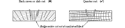
Below are diagrams showing end elevations of quarter sawn and back sawn wood.
The orientation of the medullary ray is, in my view, the important issue relating to the way wood is cut for bridge capping. If the wood is quarter cut, the medullary ray will run parallel to the top face of the bridge. Conversely, if it is back cut, the medullary ray will run perpendicular to the face of the bridge cap, and parallel to the sides of the bridge. When the medullary rays run parallel to the vertical edge of a bridge, they will be oriented practically in line with the direction of the bridge pins, into the top face of the bridge cap. Orientated in this direction, they offer little support to the bridge pins. It is therefore, more likely that the bridge wood will split adjacent to the bridge pin holes when the wood is back cut. Similarly, there will be a greater tendency for the bridge pin holes to elongate in response to the horizontal string vector forces on the bridge pins, causing the bridge pins to loosen, and tone duration to shorten. In the case of a quarter cut bridge cap, the medullary rays will be oriented in such a way that they provide genuine support to the bridge pins in a horizontal direction, but perpendicular to the support given by the long grain. We can therefore conclude, that the medullary rays offer maximum support to the bridge pins in a quarter cut bridge cap, and minimum support for the bridge pins in a back cut bridge cap.
In our own business, we previously had considerable trouble with supplies of American maple when we specified that it be quarter cut - near enough is not good enough for piano bridges. In recent years, we have been buying our American Maple as back cut boards 300mm wide, and 75mm deep, resawing these boards on our tilt-table bandsaw to obtain quarter sawn material satisfactory to our requirements, see diagram below;
Capo' Bars and Duplex Bars - their shape and effect on tone
Text to be entered here
Bearing Bars, and their position
Text to be entered here
Wire Straightening and Rubbing Down for better tone and tuning stability
The practice of straightening the piano wire is now a common procedure amongst the world's leading concert technicians. When a piano is initially strung, you will notice that the wire gently curves away, at each end of the speaking length, from the capo' bar and bridge pin respectively. Unless the wire is deliberately straightened, these curves will remain.
Wire straightening at the piano factory is generally reserved for concert pianos from the leading piano manufacturers. Commercial pianos, unfortunately, miss out on the benefits of this procedure. A marked improvement in tonal quality can be achieved by carefully straightening the wire at each end of the speaking length, so that the wire sits perfectly straight between the end points. A small punch, made of a soft material such as brass or aluminium, can be used for straightening wire. Technicians must avoid kinking the wire or carelessly damaging the bridge wood when straightening wire (we never allow the wire to be tapped down vertically). At the capo', speaking length wire is straightened tapping up from underneath, approx. 4 - 5 mm out from the bar with the action removed. At the bridge end, the wire is gently tapped as close to the horizontal as possible, in a direction towards the treble end of the piano.
When stabilising the tuning of a piano following a restring or pitch raise, the practice of rubbing down the speaking lengths with a small stick or dowel will pull-up the tension of the string segment between the bridge and the hitch plate. I use an upright hammer shank for this purpose. The historical practice of using a string-stretching wheel is not allowed in my workshop. This tool affords the technician too much leverage with which to force the string, increasing the risk of damaging the wire.
During my 1996 APTTA convention lecture, mention was made of my experience tuning the Fazioli F278 piano. This piano has rear duplex lengths which are fully adjustable and tunable. The moveable rear duplex blocks allow the technician to adjust the duplex lengths. The rear duplex is tuned when the piano is tuned. However, if a duplex block is positioned incorrectly, the duplex length tension will not be equal to that of the speaking length, and the tuning will be unstable. The technician can learn to understand the relationship between the duplex length and tuning instability. The duplex block is adjusted at subsequent tunings to correct for duplex length errors. It takes several months, making fine adjustments to the rear duplex lengths, for equal tension of the string segments, and good tuning stability to be established. I have found it interesting working with the Fazioli tuning system. When the rear duplex lengths are accurately tuned with the speaking lengths, the sound is very 'clean' and beautiful. I have rebuilt three Steinway D pianos since 1994, into which I have built a fully adjustable duplex tuning system. I am very pleased with these instruments. The tone is very good and the tuning stability is excellent.
If you have any comments or suggestions, please email us at; office@overspianos.com.au
OVERS PIANOS - SYDNEY,
AUSTRALIA
Fax (international)
61 2 9743 6563
Fax (local) 02 9743 6563
First published 4 June 2000
Last updated 20 June 2000
Copyright ©
2000, Overs Pianos.